
Wiring a car stereo is one of the most satisfying DIY jobs you can take on—until you connect the wrong wire, blow a fuse, and the radio stays dead. That’s why the smartest installers test every wire before cutting, crimping, or soldering. Testing car stereo wires with a multimeter tells you exactly which wire does what, without relying on faded wire colors or a previous owner’s sloppy splice.
By the end of this guide, you’ll know how to find constant and switched power, locate a true ground, identify speaker wires, check for shorts, and troubleshoot common stereo failures—all with one tool. No experience required, just careful probing and a little patience. For more on this, see our guide on how to test a car battery with a.
Why You Should Test Car Stereo Wires Before Anything Else
A car stereo harness looks simple: a bundle of colored wires, each with a job. But colors are not a guarantee. Manufacturers change their conventions, repair shops patch things differently, and corrosion can make a wire behave strangely.
Testing with a multimeter protects you from three common failures:
- Connecting the radio to the wrong power source, which can blow the stereo’s internal fuse or damage the circuit board.
- Grounding through a painted or corroded surface, which causes humming, static, and intermittent shutdowns.
- Connecting speaker wires out of phase, which makes the system sound thin and weak.
A multimeter also saves money. You don’t need to pay a shop to identify four wires. A few minutes of voltage and continuity checks gives you the same information. For more on this, see our guide on how to connect phone to car stereo.
Tools You Need and How to Prepare Safely
You don’t need a professional electrical kit, but you do need the right basics.
| Tool | Why You Need It |
|---|---|
| Digital multimeter | Measures DC voltage, resistance, and continuity |
| Alligator clip probe leads | Keeps both hands free while testing |
| Wire strippers and crimp tool | For clean, secure connections after testing |
| Labels or masking tape | Marks each wire once you identify it |
| Pen and paper | Notes which color goes where in your car |
| Factory or aftermarket wiring diagram | Gives you a starting point, not a final answer |
Before you start, decide which tests you’re doing. Live voltage tests require the battery connected. Continuity and short checks require the battery disconnected. Never switch directly between these modes without thinking about what you’re probing.
If you need to disconnect the battery, remove the negative cable first and tuck it aside so it cannot touch the terminal. This kills the risk of accidental shorts while you handle bare wires.
Also check your multimeter itself. A weak battery inside the meter produces inaccurate readings. Touch the probes together on the continuity mode: you should hear a beep. On the ohms mode, you should see near-zero resistance. If you see unstable numbers, replace the meter’s battery first.
Understanding the Wires Behind a Car Stereo
Most aftermarket stereos use a similar color scheme, but the factory harness in your vehicle may not match it perfectly. Treat the table below as a guide, not gospel.
| Common Wire Color | Common Function | Notes |
|---|---|---|
| Yellow | Constant 12V power | Keeps memory and clock alive when the ignition is off |
| Red | Switched 12V power | Only powered when the key is in ACC or ON |
| Black | Ground | Must connect to bare chassis metal |
| Blue or blue/white | Remote turn-on | Triggers amplifiers or a powered antenna |
| White / white-black | Front left speaker | Positive and negative pair |
| Gray / gray-black | Front right speaker | Positive and negative pair |
| Green / green-black | Rear left speaker | Positive and negative pair |
| Purple / purple-black | Rear right speaker | Positive and negative pair |
While no global rule forces every manufacturer to use these colors, standards from organizations like the International Organization for Standardization help keep aftermarket connectors reasonably consistent. Still, always confirm with the meter. In older cars, or in any vehicle with a custom audio system, the factory colors can be completely unreliable.
What the Multimeter Settings Actually Do
A digital multimeter combines several tools in one. For this job, you need only three functions:
- DC voltage – Usually marked with "V" and a straight line or dashes. Use this to find power wires.
- Resistance – Marked with the omega symbol (Ω). Use this to identify speaker wires.
- Continuity – Usually marked with a sound wave or diode symbol. Use this to check if a wire is connected end to end and to find shorts.
Your test leads plug into specific ports: black to COM, red to VΩmA. Do not use the high-current 10A port unless you know exactly why you need it. Measuring voltage with the leads in the current jack is a classic mistake that blows the meter’s fuse.
Accurate measurements start with a meter that behaves predictably. That’s why technicians treat their meters as precision tools—the electrical measurement standards published by NIST support everything from a simple continuity beep to a steady 12V reading.
Step-by-Step Guide to Testing Car Stereo Wires
Follow these steps in order. Each one builds on the last, and each one ends with a labeled wire.
Step 1: Set Up Your Multimeter Correctly
Turn the dial to DC voltage. If your meter has manual ranges, start at 20V. Car electrical systems run at roughly 12.6V, and the 20V range gives you the most useful readings without extra decimals.
Plug your leads in the right ports:
- Black lead into COM.
- Red lead into VΩmA.
Touch the two probe tips together. The meter should read 0.000V in DC mode or near-zero ohms in resistance mode. That quick test tells you the leads, probes, and meter battery are all working.

Set the meter to DC volts before touching any live wire.
Credit: www.youtube.com
Step 2: Find the Constant 12V Memory Wire
The constant wire is the one that keeps your radio’s memory alive when the key is off. Without it, you lose clock, radio presets, and Bluetooth pairings every time you park.
With the key fully off, clip the black probe to a bare metal point on the chassis. Touch the red probe to each wire in the harness one by one. The constant wire will show around 12V, even with the key out.
Label that wire as soon as you find it. A small piece of tape with "constant 12V" written on it will save you later.
If no wire shows voltage, check the car’s fuse box. A blown radio fuse is the most common reason a constant wire reads zero.
Step 3: Find the Switched 12V Ignition Wire
The switched wire tells the stereo when to turn on. Without it, the radio either stays on forever or never wakes up.
Keep the black probe on the same chassis ground. Turn the key to ACC or ON, but do not start the engine. Now test the remaining wires. The switched wire will show battery voltage only with the key in that position.
Tip: Some modern cars use data modules to control radio power, so the old-fashioned switched wire may be hidden or pulsed. If you cannot find a clean 12V switched wire, look for a fuse tap connected to an accessory circuit instead of forcing the radio to use a wire that cannot handle the load.
Step 4: Find the Ground Wire
A weak ground is the number one cause of stereo noise, dimming displays, and random shutdowns. The ground wire should connect directly to the vehicle chassis, not to another wire.
Disconnect the negative battery terminal for this test. Set the multimeter to continuity or the lowest ohms setting.
Clip one probe to a bare metal bolt or unpainted bracket on the chassis. Touch the other probe to each wire. The ground wire will beep or read near 0 ohms.
If no wire gives a solid ground, you may need to run a new ground wire to a clean chassis point. Removing paint or rust down to bare metal is often the fix.
Step 5: Identify Speaker Wire Pairs
Speaker wires come in pairs: one positive and one negative for each speaker. With the speakers still connected to the factory wiring, a good pair shows the speaker’s impedance, usually between 2 and 8 ohms.
Set the meter to ohms. Disconnect the battery first and don’t touch any power wires while in ohms mode.
Then:
- Look for wires in the same color family, like one solid white and one white with a black stripe.
- Touch one probe to each wire in the suspected pair.
- Read the resistance.
A normal speaker path shows roughly 2, 4, or 8 ohms. No speaker or a broken wire shows "OL" (over limit), meaning the circuit is open. Nearly 0 ohms means the two wires are touching each other somewhere—a short that needs to be found and repaired.
| Reading | What It Means |
|---|---|
| 2–8 Ω | Speaker pair found, wire is connected to the speaker |
| OL / infinite | No speaker, broken wire, or unplugged speaker connector |
| 0 Ω or near 0 Ω | Short circuit between the two wires |
Do this for all four speaker circuits: front left, front right, rear left, and rear right. Label each pair as you go.
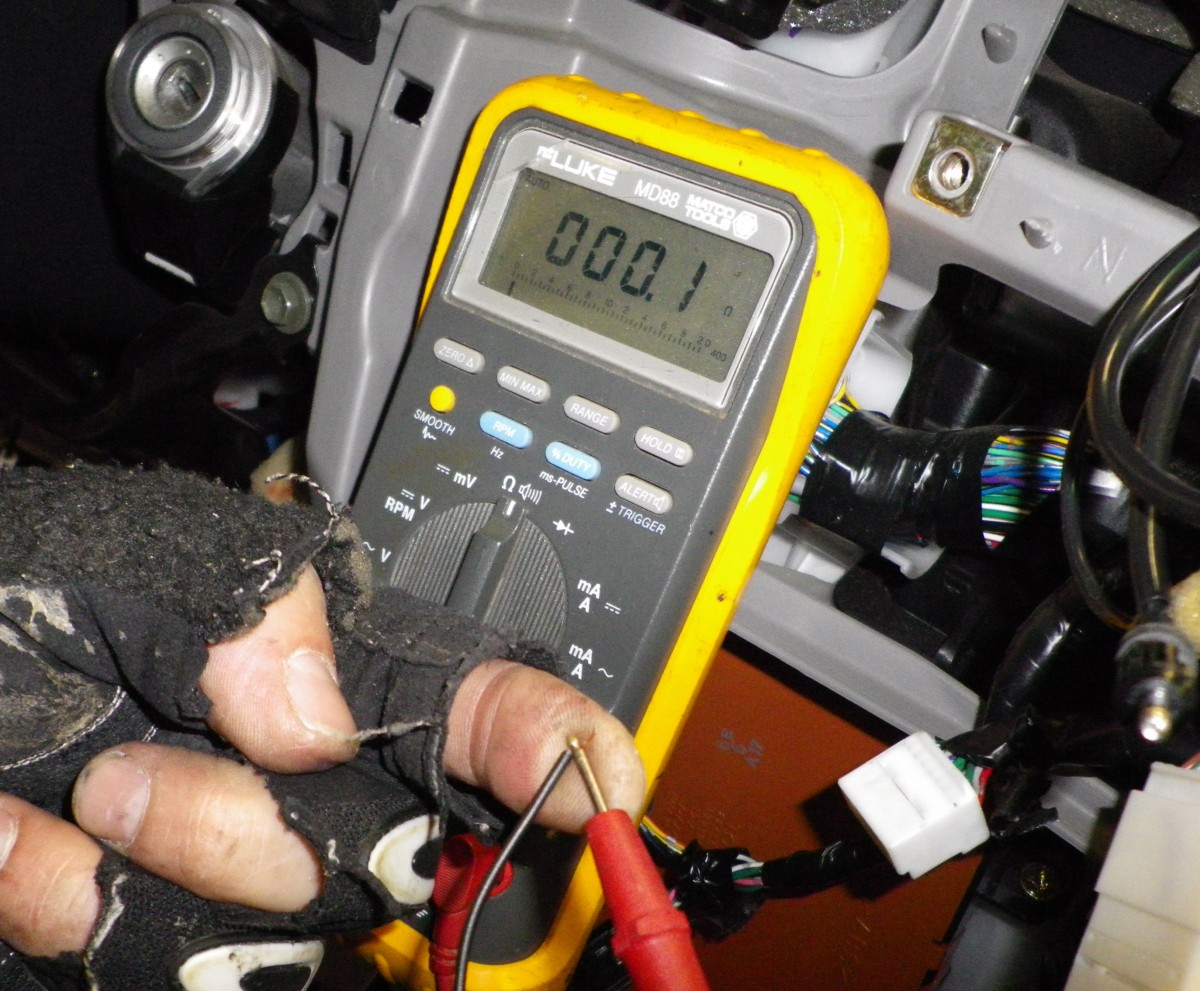
A resistance reading between two wires reveals whether they lead to the same speaker.
Credit: carstereochick.com
Step 6: Check for Shorts and Ground Leaks
Before connecting your new stereo, make sure no wire is accidentally touching ground or another power path. A short that is hidden inside the harness can damage a new head unit within seconds.
With the battery still disconnected and the stereo harness unplugged:
- Set the multimeter to continuity mode.
- Touch one probe to the constant 12V wire.
- Touch the other probe to the ground wire.
You should not hear a beep. Repeat the test between the switched 12V wire and ground, and between every speaker wire and ground.
If the meter beeps, there is a short. Trace the wiring, inspect for pinched insulation, and fix the problem before connecting anything. This single check prevents most post-installation failures.
How to Test a Mystery Wire
Suppose you find a blue wire with a white stripe behind the dash that your diagram doesn’t mention. Here’s how to identify it without guessing.
Set the meter to DC voltage. Clip the black probe to a solid chassis ground. Touch the red probe to the mystery wire, then:
- Watch the reading with the key off.
- Turn the key to ACC and watch again.
- Turn the key off and see if the voltage drops.
If the wire only shows 12V when the ignition is on, it is a switched power source. If it shows 12V only when the radio is on, it is likely a remote turn-on wire for an amplifier or antenna. If it shows battery voltage at all times, it’s constant power.
Label the wire and move on. This method is especially useful in used cars where previous owners have swapped wiring around.
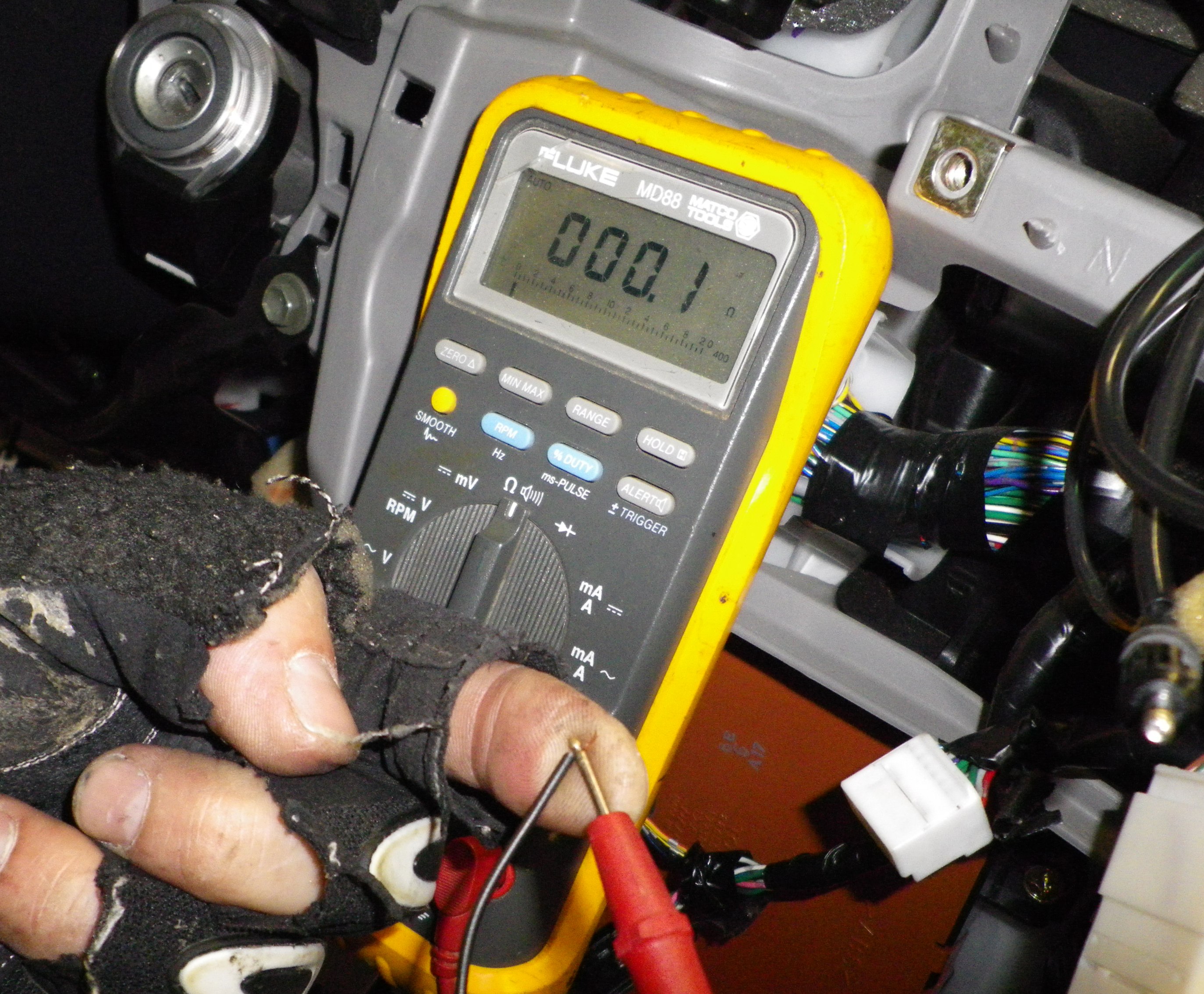
Probing an unknown wire against chassis ground reveals whether it is live, switched, or dead.
Credit: carstereochick.com
Multimeter vs. Test Light: Which Should You Use?
Some old-school installers use a 12V test light to check wires. It works for basic power testing, but it has real limitations.
| Tool | Accuracy | Continuity Testing | Risk of Damage |
|---|---|---|---|
| Digital multimeter | High | Yes | Low, because it draws almost no current |
| Test light | Medium | No | Medium; it loads the circuit and can blow fuses |
A test light is a simple bulb that draws current to light up. On sensitive circuits, that extra load can confuse modules or even damage them. A multimeter, by contrast, takes a tiny sample and doesn’t disturb the circuit.
Use a multimeter anytime you are working near expensive electronics. In practice, I’ve seen more blown fuses from test lights than from all the bad splices in the same bay.
Troubleshooting Common Car Stereo Wiring Problems
No Power to the Stereo
Start by checking the constant and switched 12V wires with the meter. Then check the stereo’s inline fuse and the vehicle’s radio fuse. A blown fuse is easy to miss because it looks fine to the eye.
Static or Humming Sound
A poor ground is the usual cause. Measure resistance between the stereo ground wire and bare chassis metal. If you see anything above 0.5 ohms, clean the contact point and try again.
One Speaker Is Silent
Test that speaker wire pair in ohms mode. If you read OL, the wire is broken, pinched, or the speaker connector is off. Gently move the harness while listening for crackles to find an intermittent break.
Stereo Turns Off When the Engine Starts
The switched 12V wire is probably connected to a circuit that drops below 12V during cranking. Reconnect it to a more stable accessory wire, or use a relay to pull power directly from the battery.
Final Checks After Installing the Stereo
Now that every wire is tested and labeled, you can make your connections with confidence. Reconnect the battery, turn the stereo on, and check each speaker using the balance and fader controls. Listen for distortion, hiss, or missing channels.
If the display is in the wrong language, take a minute to sort it out before you close the dash—you can usually fix it through the setup menu by adjusting the stereo language settings.
Keep your wiring notes somewhere accessible. If you need to troubleshoot again later, those notes are worth more than a dozen wiring diagrams.
When to Call a Professional
Testing car stereo wires is well within reach for most DIYers, but there are honest limits.
Call a professional if you see:
- Burnt or melted insulation.
- Corroded connectors that crumble when touched.
- Evidence of previous water damage behind the dash.
- Repeated blown fuses that return immediately after replacement.
- A car with a fiber-optic or MOST audio system, where the wrong probe can damage expensive modules.
There is no shame in stopping at the point where risk outweighs reward. The meter told you enough to know when you’re out of your depth.
Frequently Asked Questions
What Setting Should My Multimeter Be On for Car Stereo Wires?
Use DC voltage for power and ground tests. Use resistance or continuity mode for speaker wires and short checks. If your meter has manual ranges, set voltage to 20V DC.
Which Speaker Wire Is Positive and Negative?
In most aftermarket harnesses, the solid-color wire is positive and the striped wire is negative. But factory wiring varies. If you are unsure, check the speaker cone with a small AA battery test: touch the wires briefly to the battery, and the cone should push outward for positive polarity. Do not test powered speakers this way.
Can a Multimeter Damage My Car’s Electronics?
A multimeter is one of the safest test tools you can use because it draws almost no current from the circuit. The bigger risk is operator error: using resistance mode on a live circuit, or leaving probes on the wrong ports. Always set the meter before touching anything.
Why Does My Multimeter Show 0 Volts on Every Wire?
The most common reasons are a blown radio fuse, a weak meter battery, the key in the wrong position, or a bad chassis ground for the black probe. Touch the probes together to confirm the meter itself is working.
Where Can I Find a Wiring Diagram for My Car?
Start with the factory service manual for your exact model and year. If you don’t have that, look for a reputable aftermarket wiring database or an enthusiast forum for your vehicle. Use diagrams as a starting point, but trust the multimeter for the final answer.
Conclusion
Testing car stereo wires with a multimeter is not about being an electrician. It’s about keeping your installation safe, your sound clean, and your costs low. One careful test can save you from a blown fuse, a damaged head unit, or an afternoon of chasing a mysterious static hum.
Your next step is simple: set your meter to 20V DC, clamp the black probe to clean metal, and verify the constant and switched 12V wires in your car before you connect anything. That 15-minute check turns guessing into knowledge.
For more hands-on projects and practical car care advice, browse the other vehicle DIY guides on the Motor Rankings blog.

Leave a Reply